Drawing or photo
to mold-ready 3D.
Send a drawing, a photo or a sample. AI builds the 3D model first. Once you approve it, we split the parts, plan the molds and deliver CAD your mold maker can open.

Figures from real projects we have done.
Send what you have.
Get mold-ready files.
Drawings, photos, samples or existing 3D files all work. What you get back is ready to print, to show your customer and to make molds from.
You send Input
- Design drawingsRenders or design views
JPGPNGPDF
- One photoOne front view is enough
JPGPNGHEIC
- Sample photosHave a sample? Shoot a few
JPGHEIC
- 3D filesStart from an existing model
STLOBJGLB
- Vector artworkIllustrator files convert too
AIPDFSVG
You get Output
STL
3D-printed prototypeCheck the look and feelGLB
Color modelRotate it on a phoneSTEP
Solid partsEvery part, plus the assemblyIGS
SurfacesWidely used by mold makersDXF
2D drawingsFlat outlines and views
Only drawings to start.
Mold-ready at the end.
A kids' trike toy. The factory had no 3D model and no sample, only the designer's drawings.

 DrawingAI 3D
3D first,
matched to the drawing.
Five angles, each checked against the drawings. Parts are split only after the shape is approved.
- Print a prototype straight from the STL
- Send the GLB for your customer to view on a phone
- Your customer approves the shape via a link
Five angles, side by side
Top: the factory's drawingBottom: AI 3D, same angle
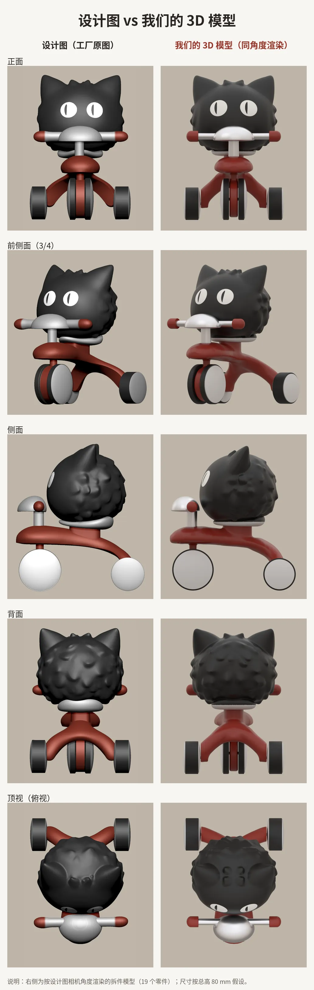 DrawingAI 3D
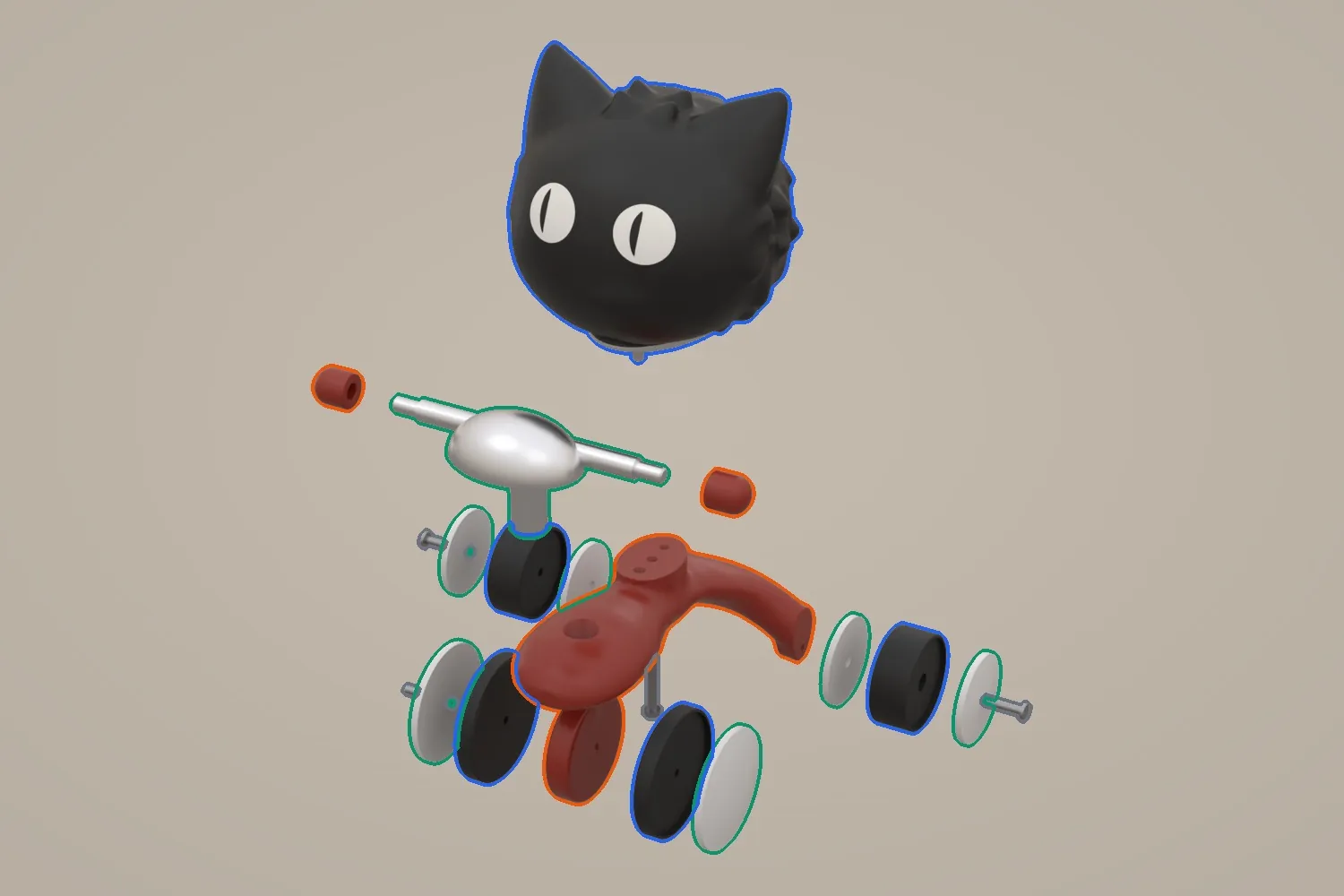 Exploded view · 19 parts
19 parts,
3 molds by color.
- ① Black moldCharacter head + wheels
- ② Brick-red moldFrame + grips
- ③ Light-gray moldHandlebar + hub caps
- Bought-in hardware × 43 steel axles, 1 screw, no mold needed
Outline color shows the mold. Each shot makes one whole trike's parts in that color.
Predicted production order
- Injection3 molds
- WeldingHead shells
- Spray paintGray seat ring
- Pad printEyes
- Chrome platingHandlebar
- AssemblyAxles, screw
CAD your mold maker
can open right away.
One STEP and one IGS for every part, plus an assembly STEP. They open in UG, Rhino and SolidWorks.
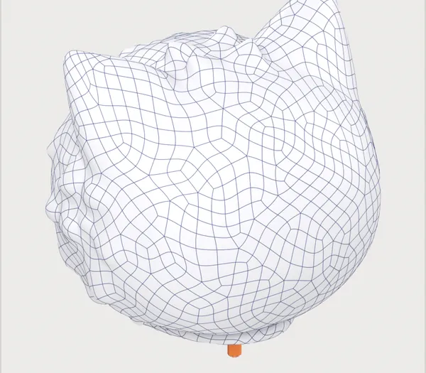
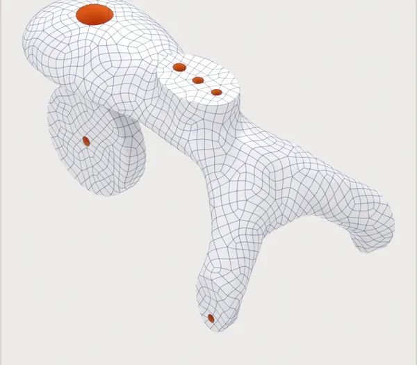
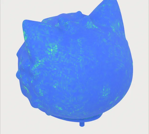
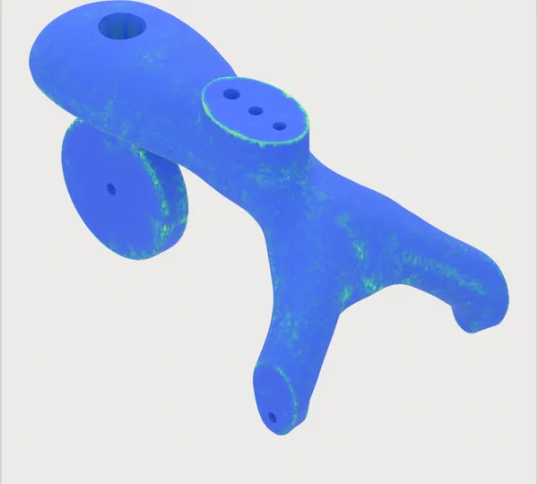
NoteSize is assumed at 80 mm tall until the factory confirms it. Draft angles, shrinkage, tolerances and gates are set together with your mold maker before tooling.
See how it splits
before cutting steel.
For every part, AI marks the opening direction, parting line, side actions (slides) and gate. Your mold maker can size up the tool from one picture.
Side actions (slides)
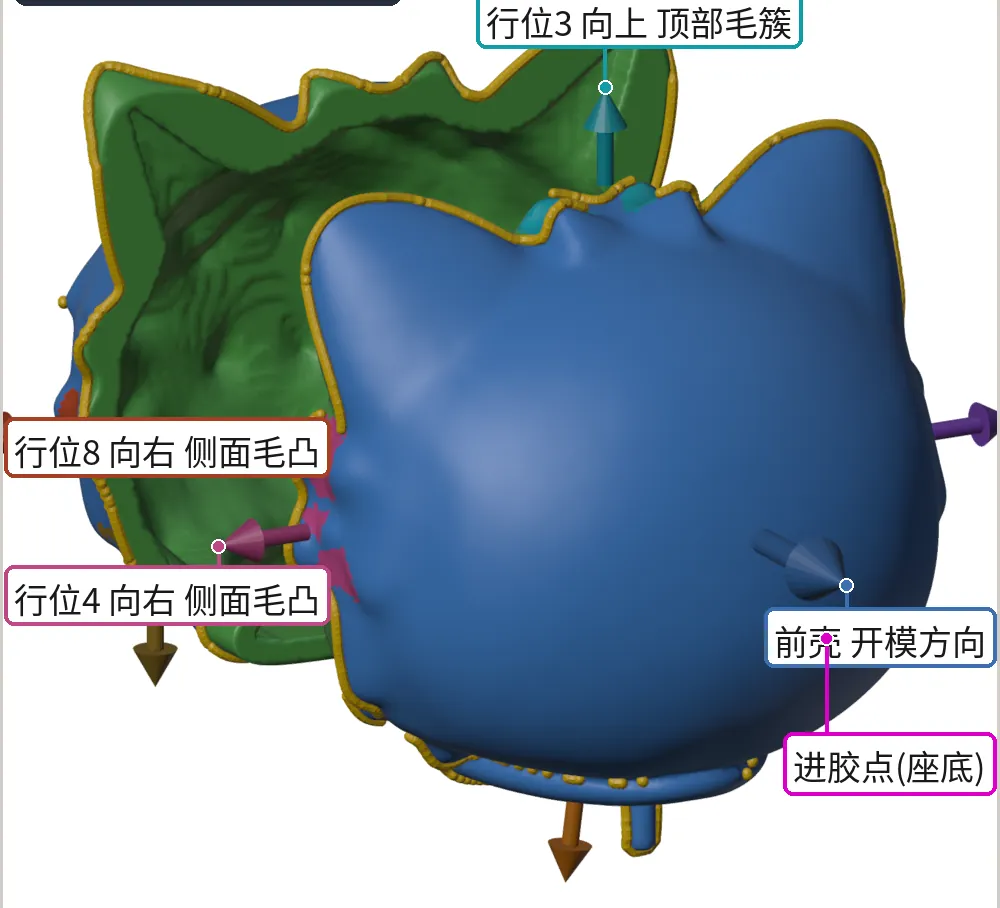
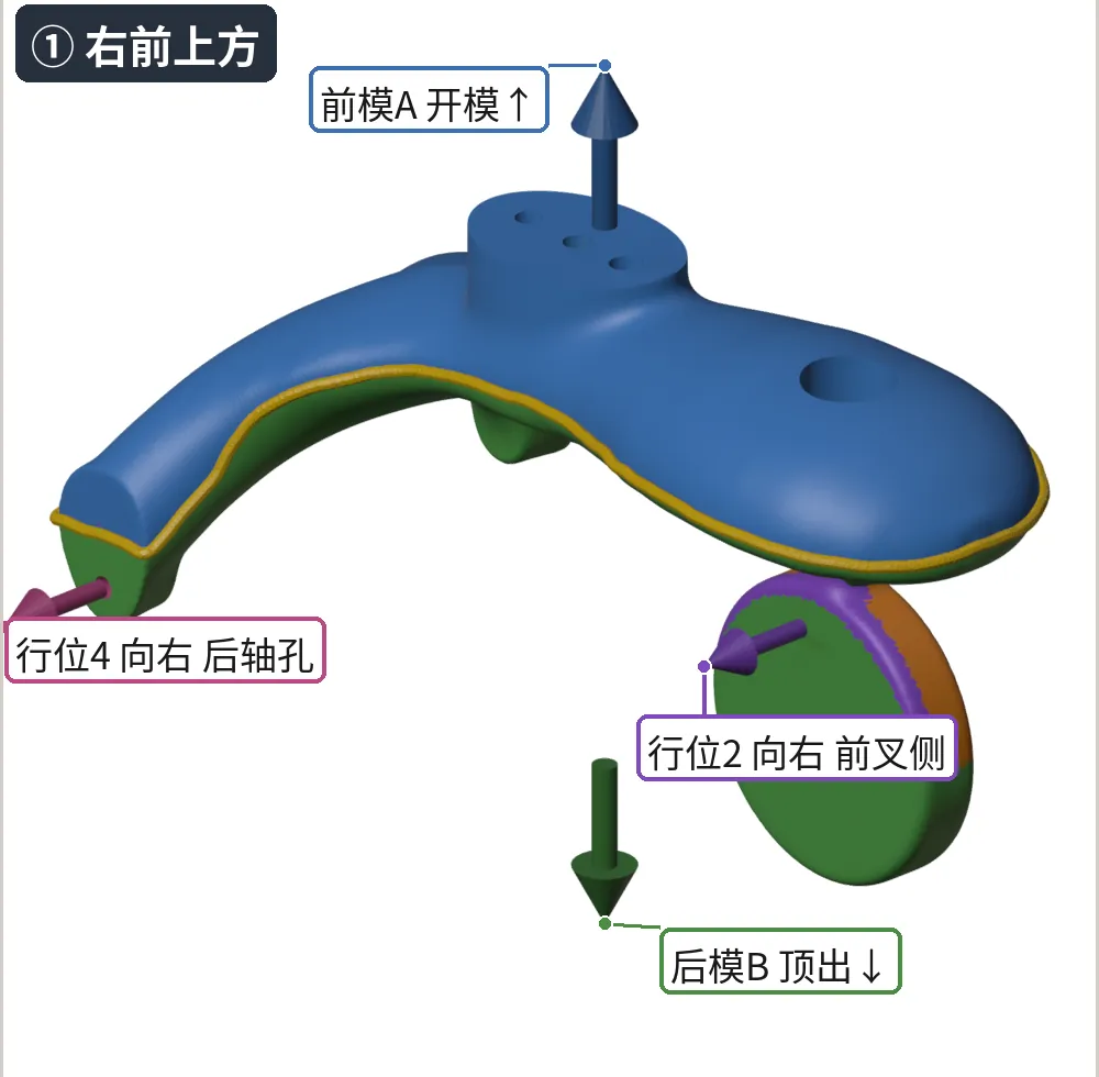
One customer photo.
A full-color 360° figurine.
The front follows the photo. The back, which the photo can't show, is inferred by AI. Before molding, have a sculptor refine the details.
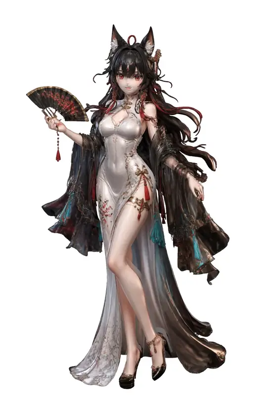
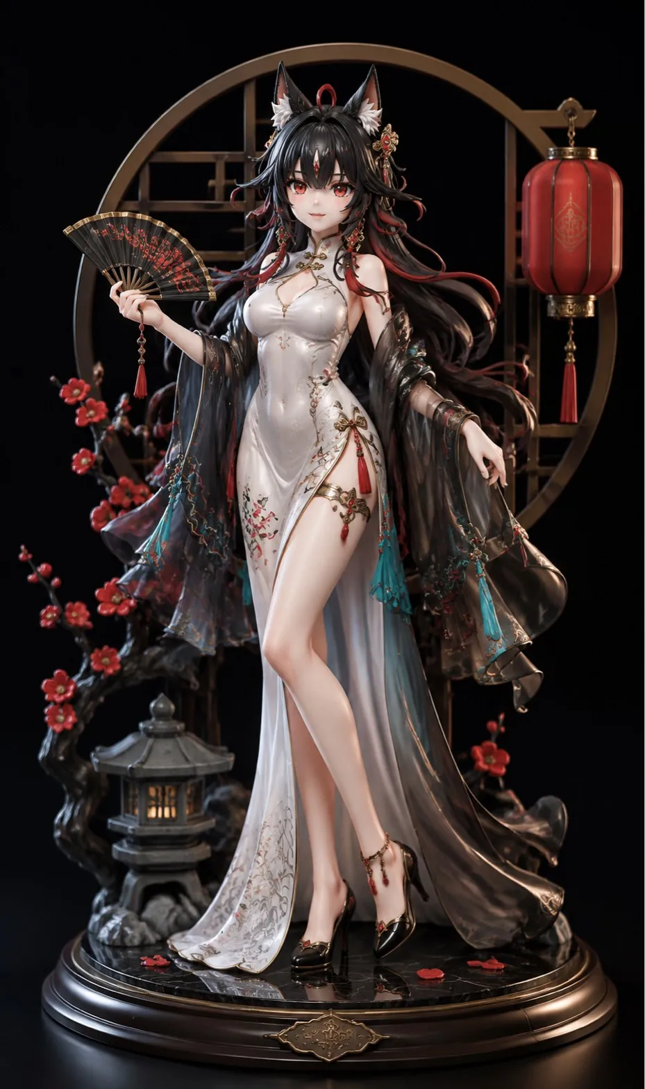
From one photo
to mold-ready CAD.
- 6 candidatesSix 3D options from the same photo
- Best silhouette match86% match with the photo's outline
- Color and 360° videoThe customer spins it and approves the shape
- CAD surfaces24,600 patches, zero free edges
- Independent error checkMax 0.22 mm, on thin sleeve edges
Filled in by AIThe back and sides the photo doesn't show
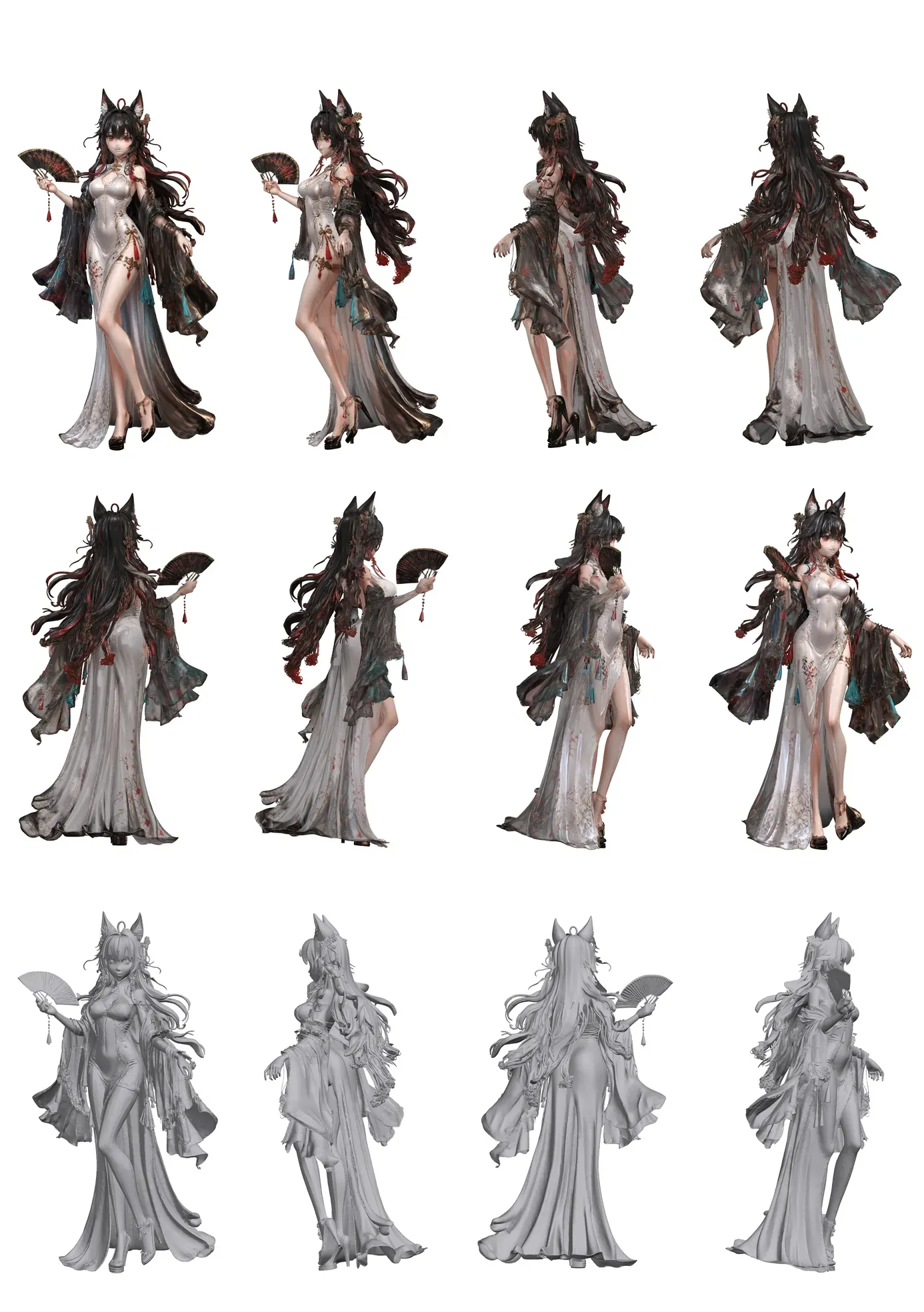
White clayFront, left, back and right, shape only
NoteAnything the photo can't show is inferred by AI, not measured. For a figurine headed for molding, we recommend having a sculptor refine the details before the CAD step.
One photo,
3D in 10–15 min.
It all runs on a phone: no software to install, no Windows PC. Send your customer a link; they rotate the model on their phone and approve it or ask for changes.
- UploadJust one photo
- 10–15 minAI builds the 3D
- Send a linkOpens on a phone
- ApprovedOr edits requested
- STL for printing, GLB for color
- No app for your customer: they just open the link
Illustration: the 3D page your customer sees on a phone.
Not just injection.
Split for your process.
Parts and molds are planned around the process you use. CNC for molds and prototypes, 3D printing for quick samples.
- 注塑
Injection molding
Hard plastic parts, the most common in toys.
- 搪胶
Slush molding
Hollow soft-vinyl figures.
- 吹塑
Blow molding
Bottles, balls and other hollow parts.
- 压铸
Die casting
Alloy model cars and metal parts.
- 吸塑
Thermoforming
Blister packs and thin shells.
See the 3D-printed mold
AI-designed, 3D-printed molds: within 1 day, a few hundred RMB. - 硅胶模压
Silicone molding
Compression-molded silicone and soft rubber parts.
- 冲压
Stamping
Sheet-metal parts and hardware.
- CNC
CNC machining
Machines molds and prototypes.
- 3D 打印
3D printing
Quick prototypes to check the look and feel.
Next: from 3D
all the way to production.
These tools are in development. We will update this page as each one goes live.
- Coming soon
Automatic mold layout
Which parts share a mold, and how they sit.
- Coming soon
CNC job planning
Plans CNC jobs for molds and prototypes.
- Coming soon
Injection settings
Suggested trial settings by part and material.
- Coming soon
Spray-paint masks
Paint masks designed straight from the 3D model.
- Coming soon
Visual inspection
Cameras check parts and flag visible defects.
- Coming soon
Self-serve part splitting
Upload a 3D file; split parts, plan molds and check the fit yourself.
How accurate is 3D from a single photo?
The front follows the photo; in the figurine case the silhouette matched the photo by 86%. The back and sides are inferred by AI, so for molding we recommend having a sculptor refine the details first.
Can my mold maker use your files directly?
Every part comes as STEP and IGS, plus an assembly STEP. They open in UG, Rhino and SolidWorks. Draft angles, shrinkage, tolerances and gates are set together with your mold maker before tooling.
What if I don't have dimensions?
We start from an assumed size, for example 80 mm tall for the kids' trike, and finalize it once the factory confirms.
Do I need to install any software?
No. Photo to 3D runs on a phone in about 10–15 minutes, with no Windows PC needed. Your customer opens a link to rotate the model and approve it or ask for changes.
Can I get a prototype first?
Yes. The STL file can go straight to a 3D printer, so you can check the look and feel before paying for molds.
How do I send my files?
Email them to contact@mofa-ai.com. Photos as JPG, PNG or HEIC; 3D files as STL, OBJ or GLB; artwork as .ai, PDF or SVG.
Send us your product.
See it, then decide.
Drawings, photos, samples or 3D files all work. Tell us what you make and where you are stuck, and we will show you the result on your own product.