See it formed
before you print.
Heated sheet stretches, and the printed art shifts with it. AI works out how every area stretches and outputs compensated artwork in about 30 minutes, so the art lands where it should.
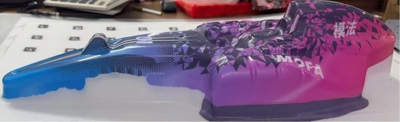
 AI prediction· before formingPhoto· after forming
Figures from real projects; “was” reflects common industry practice and quotes.
Stretch the sheet,
shift the print.
Heated sheet goes soft and is pulled onto the mold, and every area stretches by a different amount. However accurately you print the flat sheet, the art ends up in the wrong place. Compensated artwork works out the shift in advance and corrects the art before you print.
Five steps to
compensated artwork.
The factory forms one calibration sheet and takes a set of photos. AI does the rest.
- 01
Calibration sheet
Print our sheet: random dots, 32 markers.
- 02
Form
Use your production material and machine.
- 03
Photograph
48 photos on the scan rig, or 20–30 with a phone.
- 04
AI measures stretch
It finds every dot and maps the stretch.
- 05
Artwork + preview
Compensated artwork and the predicted look of each cavity.
The sheet that
measures stretch.
This sheet is the core of the method: random dots cover it edge to edge, plus 32 ArUco markers. After forming, AI finds every dot in the photos and knows how far each area stretched.
- Size
- 530 × 740 mm
- Markers
- 32 ArUco
- Dots
- Random, all over
- Layout
- 4-up · ABCD
 ABCD
The core hardware:
an AI scan rig.
A rig we designed ourselves. The positioning disk sits on an electric turntable, two cameras shoot from low and high, and one turn gives 48 photos in about 2 minutes. The ArUco markers let AI pin down every point.

 Camera B · high
 Disk · Ø1000 mm
One round,
about 2 minutes.
- Place the sheetThe formed calibration sheet goes in the middle of the disk
- One full turnThe turntable stops every 15°, 24 stops in all
- Two cameras, one shot eachAt every stop, one low and one high: 48 photos
- AI computes the stretchIt pins down every point and works out how each area stretched
No rig?
Use a phone.
No need to buy equipment first. Take 20–30 photos like this and upload the original files.
- Get the whole sheet in frame, all four corner markers visible
- Walk around it twice: one circle high, one low
- Use the 1× main camera, flash off
- Upload the original files, uncompressed
Prediction vs part,
point by point.
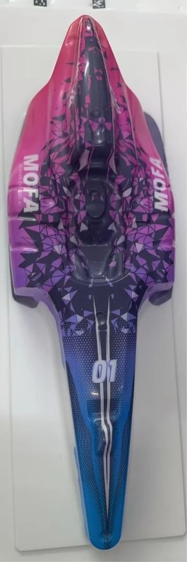
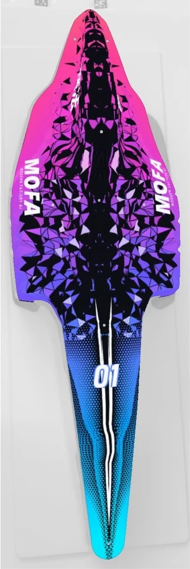
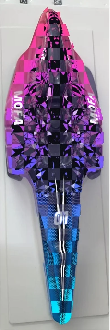
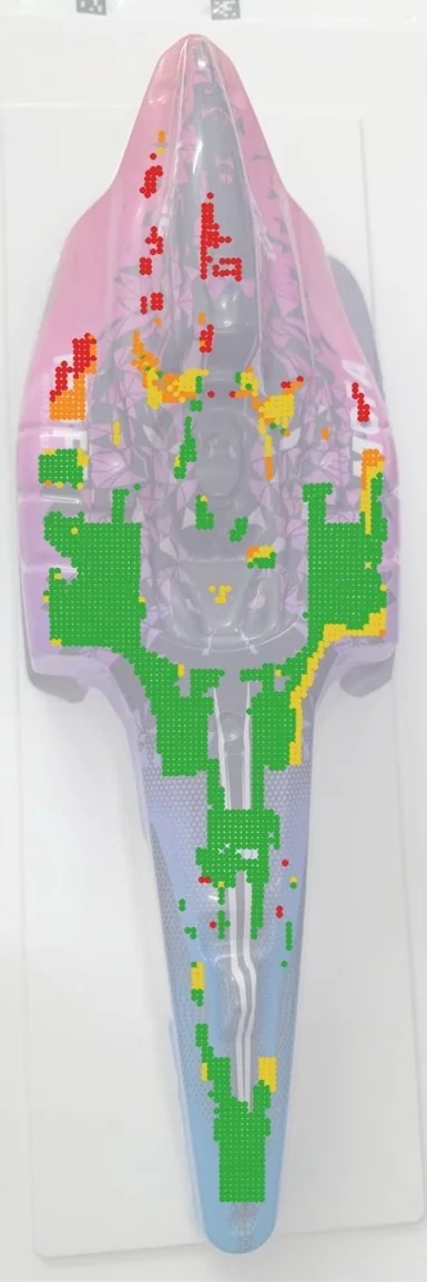
F1 car shell from above: photo, AI prediction, the two overlaid, and the error map, colored by how far off each area is.
See the error
at a glance.
- < 0.5 mmGreen
- 0.5–1 mmYellow
- 1–2 mmOrange
- > 2 mmRed
Red areas (over 2 mm) are still being improved. We show them as they are.
- See each cavity's formed look before printing
- Error estimated before and after compensation
- A physical sample has the final say
Files you can
use right away.
On a multi-up sheet, every cavity is compensated and previewed separately.
- PDFCompensated artwork100% size
- PDFWhite-ink base layerOptional, for a white underprint
- TIFCMYK print fileTIF in CMYK, for your printer
- Predicted look per cavitySee the formed result before printing
- Error estimateBefore vs after; a sample has the final say
Design in 3D,
print it flat.
No more guessing on a flat layout. Paint on 5 templates, AI wraps them onto the 3D body for you to check, and the compensated flat artwork comes out ready to print.
-
01
Paint 5 templates
Top, both sides, front and rear.
-
02
Mapped onto the 3D body
Each face snaps into place.
-
03
3D preview and video
Watch the body turn before you print.
-
04
Compensated flat artwork
Stretch built in, ready to print.
AI-designed,
3D-printed molds.
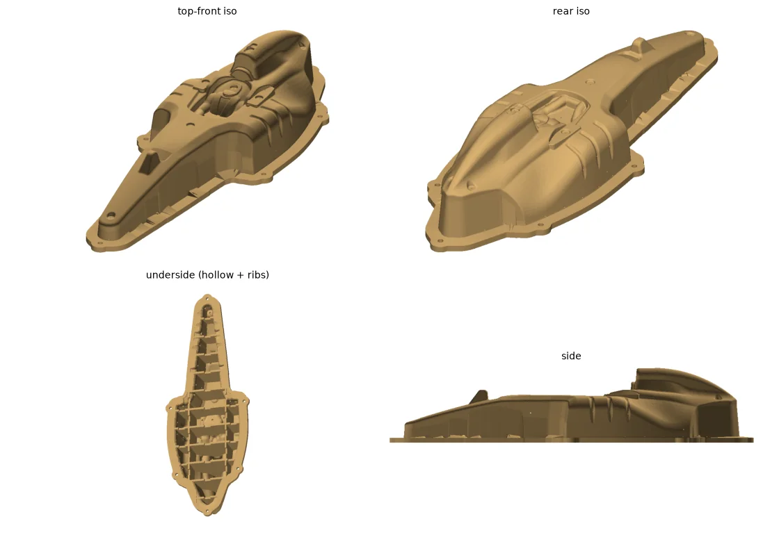
No more waiting for copper or aluminum molds. AI adds draft angles, places vent holes and hollows the back with ribs. The mold is 3D printed in a new heat-resistant resin.

 F1 car shell mold · 37 cm long
No software.
Just a link.
We send the factory a link on WeChat with shooting instructions. The factory uploads photos and leaves messages right there. No app to install.
- We send a linkOn WeChat, with shooting instructions
- Upload photos, leave notesRight in the web page
- Recalibrate after changesNew material or machine settings: form one calibration sheet and photograph it
Common
questions.
Anything else? Email us.
Can I start without the scan rig?
Yes. Take 20–30 photos with a phone: the whole sheet in frame with all four corner markers visible, one high circle and one low circle, 1× main camera, flash off. Upload the original files.
What about 4-up or 6-up sheets?
Every cavity is calculated and compensated on its own, with its own predicted look.
How long does it take?
About 30 minutes from uploaded photos to compensated artwork.
Do I redo it if I change material or machine settings?
Recalibrate once: form one calibration sheet, photograph it, and carry on.
Which files do I get?
Compensated artwork PDF at 100% size, an optional white-ink base layer PDF and a CMYK TIF, plus the predicted look of each cavity and an estimate of position error before and after compensation.
How accurate is the prediction?
We compare the prediction with photos of the real part point by point and color the error at 0.5, 1 and 2 mm. Red areas (over 2 mm) are still being improved. Error estimates are predictions; a physical sample has the final say.
Can you make the thermoform mold too?
Yes. AI designs the mold with draft angles, vent holes and a hollow, ribbed back, and it is 3D printed in a resin rated to 250°C. Ready within a day, for a few hundred RMB.
Send us your product.
See it, then decide.
Drawings, photos, samples or 3D files all work. Tell us what you make and where you are stuck, and we will show you the result on your own product.